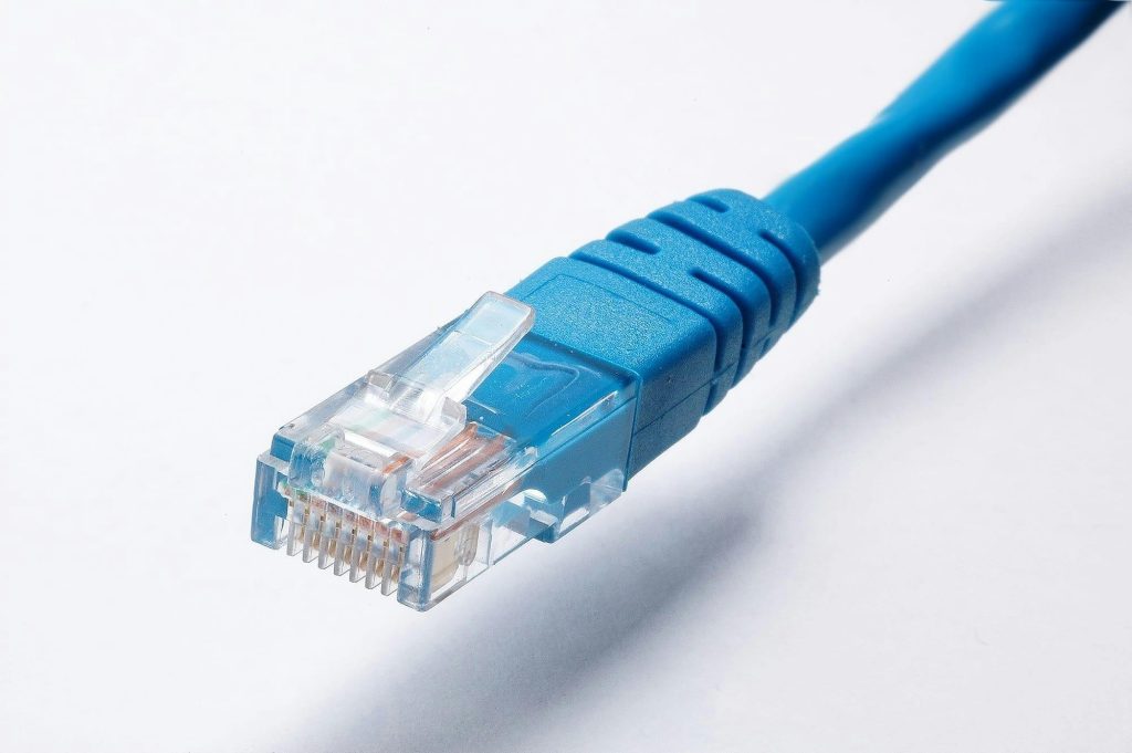
Ethernet networks are the backbone of modern communication systems, providing connectivity in enterprise, industrial, and home networks. Proper cabling and pin configurations play a crucial role in ensuring reliable data transmission. This article explains Ethernet pinouts, their significance, and how MDI/MDX (Medium Dependent Interface/Auto-Medium Dependent Interface Crossover) simplifies connectivity by automatically adjusting connections between devices.
Ethernet Pinouts
Ethernet cables use twisted-pair wiring with different pin configurations depending on the type of connection. The two primary standards for Ethernet wiring are T568A and T568B, defined by the TIA/EIA-568 standard.
T568A and T568B Pinouts
Ethernet cables consist of eight conductors arranged in four twisted pairs:
| Pin | T568A Color | T568B Color | Function |
|---|---|---|---|
| 1 | White/Green | White/Orange | Transmit + (TX+) |
| 2 | Green | Orange | Transmit – (TX-) |
| 3 | White/Orange | White/Green | Receive + (RX+) |
| 4 | Blue | Blue | Unused (Fast Ethernet) / Bi-Directional (Gigabit Ethernet) |
| 5 | White/Blue | White/Blue | Unused (Fast Ethernet) / Bi-Directional (Gigabit Ethernet) |
| 6 | Orange | Green | Receive – (RX-) |
| 7 | White/Brown | White/Brown | Unused (Fast Ethernet) / Bi-Directional (Gigabit Ethernet) |
| 8 | Brown | Brown | Unused (Fast Ethernet) / Bi-Directional (Gigabit Ethernet) |
Straight-Through vs. Crossover Cables
- Straight-through cables use the same pinout (T568A or T568B) on both ends, typically used to connect devices of different types (e.g., a PC to a switch).
- Crossover cables use T568A on one end and T568B on the other, used for direct device-to-device connections (e.g., PC to PC, switch to switch without an uplink port).
The Challenge: Connecting Different Ethernet Devices
In traditional Ethernet networks, devices require specific cabling types to establish a connection correctly. For example:
- A PC connecting to a switch requires a straight-through cable.
- A PC connecting to another PC requires a crossover cable.
This dependency on specific cable types led to connectivity issues, requiring users to carry both straight-through and crossover cables or manually switch ports.
MDI/MDX: Solving the Connectivity Challenge
What is MDI/MDX?
- MDI (Medium Dependent Interface): The default Ethernet port configuration, where TX pins transmit and RX pins receive.
- MDX (Medium Dependent Interface Crossover): A technology that automatically detects and corrects incorrect cabling by internally swapping TX and RX pairs.
How MDX Works
Modern Ethernet switches and routers implement Auto-MDIX (Automatic MDI/MDX) to detect and adjust for improper cabling. This means:
- Devices automatically switch between MDI and MDX modes.
- No need for dedicated crossover cables—a standard Ethernet cable works for all connections.
- Reduces installation complexity and human errors in network setup.
Advantages of Auto-MDIX
- Eliminates crossover cable requirement.
- Simplifies network installations and troubleshooting.
- Improves flexibility by allowing any Ethernet cable to work in any scenario.
- Reduces the need for manual cable swapping or port configuration.
Conclusion
Ethernet pinouts (T568A and T568B) define the wiring standard for network cables, but differences in device types historically required careful selection between straight-through and crossover cables. The introduction of MDI/MDX and Auto-MDIX has simplified network setups by allowing Ethernet devices to automatically adjust their pin configurations, ensuring seamless connectivity and reducing potential errors.
With modern networking equipment supporting Auto-MDIX, users no longer need to worry about crossover cables, making Ethernet networking more flexible, efficient, and user-friendly.